Get 30 Day NX CAM Trial
Experience NX CAM with a free trial today.

Learn more about NX CAM by exploring our downloads. NX CAM is recognized as a leader in the CAM category - start your Journey today.
-3.png)

Experience NX CAM with a free trial today.
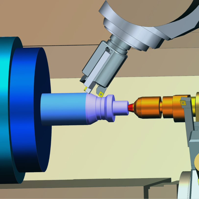
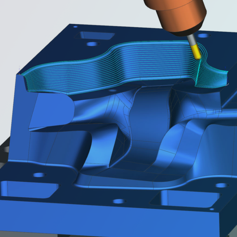
Generate high-performance machining operations to increase material removal rates, improve surface quality and extend tool life.
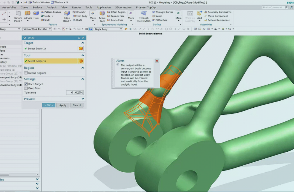
Complete jobs on spec and on time by using one CAD/CAM software to connect part manufacturing — from 3D models to precision machined parts.
Experience NX CAM with a free trial today.
%2015%25-4.png)

%2015%25-5.png)

%2015%25-16.png)