Get in Touch for More Insights
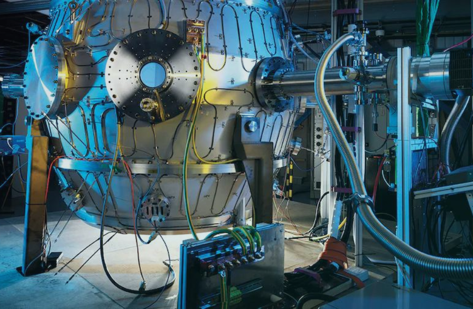
Excellence and efficiency in the manufacturing industry.


%2035%25.jpg)
With our advanced solutions that are purpose-built to transform operations by fostering efficiency, safety, and innovation, you can achieve full digitalisation in manufacturing processes.
VIEW ALL CASES.png)
.png)


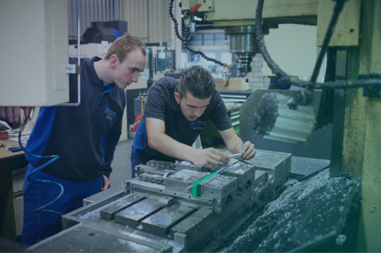
Emixa has decades of experience in driving innovation across the Manufacturing industry. We serve a range of businesses, from SMB's to large OEM's. Explore our downloads to find out how.
-3.png)

Excellence and efficiency in the manufacturing industry.
.png?width=1911&height=394&name=Ontwerp%20zonder%20titel%20(3).png)
%2015%25.png)